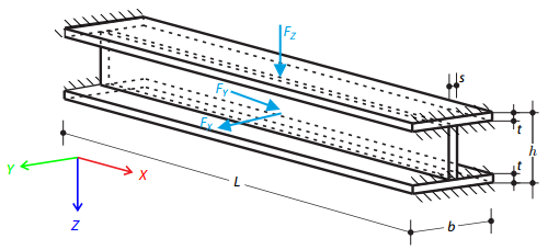
Une structure constituée de treillis profilés en I est soutenue aux deux extrémités par des appuis à ressort et chargée par les efforts transversaux. Le poids propre est négligé dans cet exemple . Déterminez la flèche de la structure, le moment fléchissant, l'effort normal dans des points d'essai donnés et la flèche horizontale de l'appui du ressort.
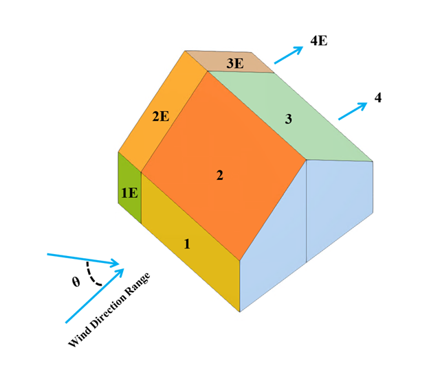
Dans l'exemple de validation actuel, nous étudions le coefficient de pression du vent (Cp) pour les barres structurelles principales (Cp,ave ) et les barres structurelles secondaires telles que les systèmes de bardage ou de façade (Cp,local ) d'après le NBC 2020 {%}#Références à [1]]] et Base de données de soufflerie japonaise pour les bâtiments peu élevés avec une pente de 45 degrés. Dans la partie suivante, nous vous décrivons les paramètres recommandés pour les toitures-terrasses 3D avec des avant-toits pointus.
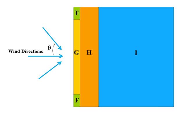
Dans l'exemple de validation actuel, nous examinons la valeur de la pression du vent pour le calcul général de la structure (Cp,10 ) et le calcul de structure local tel que les systèmes de bardage ou de façade (Cp,1 ) d'après un exemple de toiture-terrasse de l'EN 1991-1-4 { %/?#Refer [1]]] et Base de données de soufflerie japonaise . Dans la partie suivante, nous vous décrivons les paramètres recommandés pour les toitures-terrasses 3D avec des avant-toits pointus.
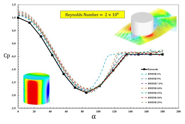
Les normes disponibles, telles que l'EN 1991-1-4 [1], l'ASCE/SEI 7-16 et le CNB 2015 présentent des paramètres de charge de vent tels que le coefficient de pression du vent (Cp ) pour formes de base. Le point important est de savoir comment calculer les paramètres de charge de vent plus rapidement et avec plus de précision plutôt que de travailler sur des formules normatives fastidieuses et parfois compliquées.
Un portique courbe appelé « portique de Lee » est fixé aux extrémités et chargé par une force concentrée au point A. Le ratio de flèche au point A pour les pas de charge donnés doit être déterminé. Le problème est défini selon les critères de référence non-linéaires NAFEMS.
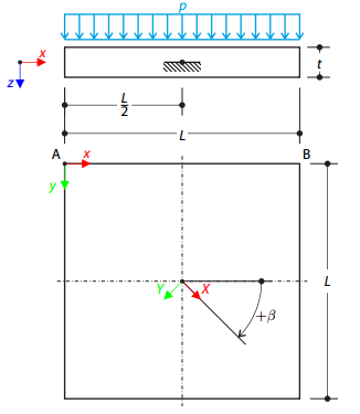
Une plaque orthotrope carrée en couches est complètement encastrée en son point central et soumise à la pression. Comparons les flèches des coins de plaque pour vérifier l'exactitude de la transformation.
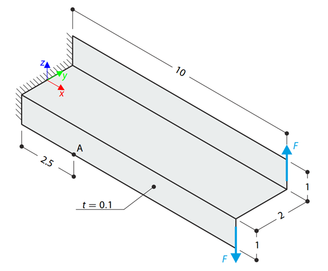
Un porte-à-faux de section en Z est entièrement fixé à ses extrémités et chargé par un moment qui, dans le cas d'un modèle en coque, est représenté par quelques efforts tranchants. Déterminez la contrainte axiale au point A (au milieu de la surface). Le problème est défini selon la norme NAFEMS.

Une force axiale excentrée s'exerce sur une console constituée d'une barre arrondie. Determine the maximum vertical deflection of the console using the geometrically linear and second-order analysis.
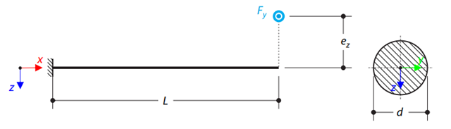
Une force transversale excentrée s'exerce sur une console constituée d'une barre ronde. Determine the maximum deflection and maximum twist of the console using the geometrically linear analysis.
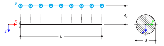
Une charge excentrique uniforme s'exerce sur une console constituée d'une barre ronde. Determine the maximum deflection and maximum twist of the console using the geometrically linear analysis.
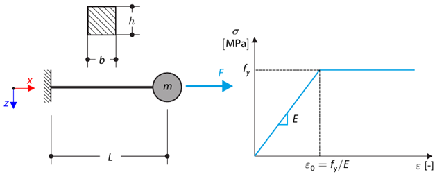
Cet exemple de vérification est basé sur l'exemple de vérification 0122. A single-mass system without damping is subjected to an axial loading force. An ideal elastic-plastic material with characteristics is assumed. Determine the time course of the end-point deflection, velocity, and acceleration.
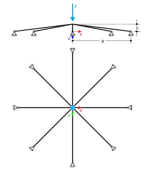
A symmetrical shallow structure is made of eight equal truss members, which are embedded into hinge supports. The structure is loaded by a concentrated force and alternatively by imposed nodal deformation over the critical limit point when the snap-through occurs. Imposed nodal deformation is used in RFEM 5 and RSTAB 8 to obtain the full equilibrium path of the snap-through. Le poids propre est négligé dans cet exemple. Determine the relationship between the actual loading force and the deflection, considering large deformation analysis. Evaluate the load factor at the given deflections.

Un tuyau de section tubulaire est chargé par une pression interne. This internal pressure causes axial deformation of the pipe (the Bourdon effect). Determine the axial deformation of the pipe endpoint.
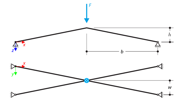
A structure is made of four truss members, which are embedded into hinge supports. The structure is loaded by a concentrated force and alternatively by imposed nodal deformation over the critical limit point, when snap-through occurs. Imposed nodal deformation is used in RFEM 5 and RSTAB 8 to obtain the full equilibrium path of the snap-through. Le poids propre est négligé dans cet exemple. Determine the relationship between the actual loading force and the deflection, considering large deformation analysis. Evaluate the load factor at given deflections.
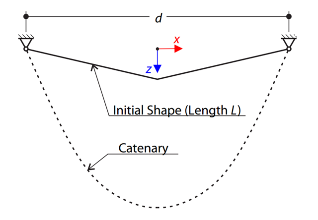
Un câble très rigide est suspendu entre deux appuis. Determine the equilibrium shape of the cable (the catenary), consider the gravitational acceleration, and neglect the stiffness of the cable. Verify the position of the cable at the given test points.
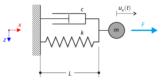
Un système à un degré de liberté avec un amortisseur est soumis à une force de charge constante. Determine the deflection and velocity of the dashpot endpoint in the given test time.
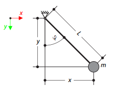
Le pendule mathématique est composé d'une corde de poids zéro et d'un point de masse à son extrémité. The pendulum is initially deflected. Determine the angle of the rope at the given test time.
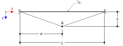
Une chaîne mince est mise en tension par une déformation initiale et fléchie. Determine the deflection of the test point at the given test times.
Le but de cet exemple est de démontrer un processus irréversible causé par une friction. After the loading and unloading, the end-point is in a different position than where it was at the beginning. Determine the movement of the node in the X direction.
Un mur en maçonnerie est exposé à une charge répartie au centre de sa partie supérieure. The Isotropic Masonry 2D material model is compared with the Isotropic Linear Elastic model, with surface stiffness property Without Tension in the nonlinear calculation.
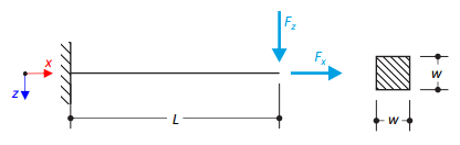
Un porte-à-faux est chargé par une force transversale et un effort normal à l'extrémité droite et est entièrement encastré à l'extrémité gauche. The problem is described by the following set of parameters. The problem is solved by using the geometrically linear analysis, second-order analysis, and large deformation analysis.
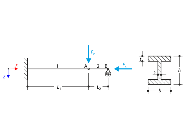
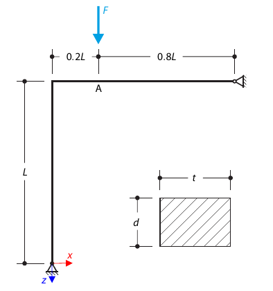
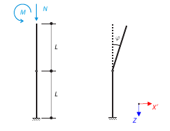
A structure made of an I-profile is fully fixed on the left end and embedded into the sliding support on the right end. The structure consists of two segments. Le poids propre est négligé dans cet exemple. Determine the maximum deflection of the structure, the bending moment on the fixed end, the rotation of segment 2, and the reaction force at point B by means of the geometrically linear analysis and the second-order analysis. The verification example is based on the example introduced by Gensichen and Lumpe.
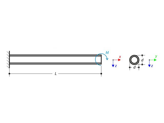
Un porte-à-faux est chargé par un moment à son extrémité libre. Using the geometrically linear analysis and large deformation analysis, and neglecting the beam's self-weight, determine the maximum deflections at the free end. The verification example is based on the example introduced by Gensichen and Lumpe.
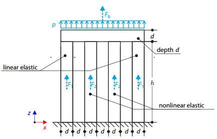
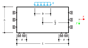
Quatre poteaux sont encastrés en bas et reliés par un bloc rigide en haut. The block is loaded by pressure and modeled by an elastic material with a high modulus of elasticity. The outer columns are modeled by linear elastic material and the inner columns by a stress-strain diagram with decaying dependence. Assuming only the small deformation theory and neglecting the structure's self-weight, determine its maximum deflection.
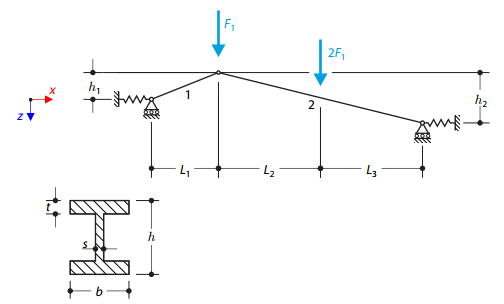
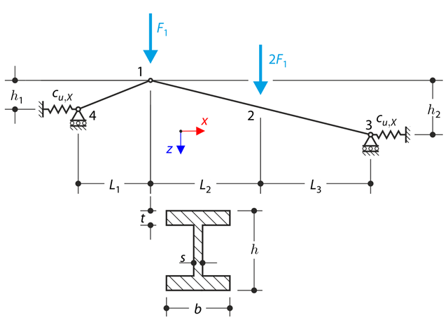
A structure made of I-profile trusses is supported on both ends by spring sliding supports and loaded by transversal forces. Le poids propre est négligé dans cet exemple. Determine the deflection of the structure, the bending moment, the normal force in the given test points, and the horizontal deflection of the spring supports.
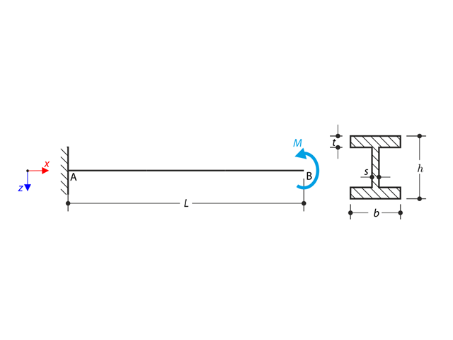
Un porte-à-faux profilé en I est supporté à l'extrémité gauche et chargé par un couple. The aim of this example is to compare the fixed support with the fork support and to investigate the behavior of some representative quantities. Comparison is also made to the solution by means of plates. Small deformations are considered, and the self-weight is neglected. Determine the rotation in the midpoint of the cantilever, and in case of the member entity with warping, determine the values of the primary torsional moment, the secondary torsional moment, and the warping moment both on the left end (point A) and the right end (point B).
Considérez un assemblage tubulaire d'un échafaudage soumis à un effort normal et un moment. Self-weight is not considered. The material of the tube is idealized as perfectly rigid. All geometrical non-linearities are ignored. Determine the angle of deflection.
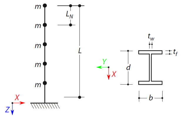
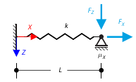
A cantilever beam with an I-beam cross-section of length L is defined. The beam has five mass points with masses m acting in the X-direction. le poids propre est négligé. The frequencies, mode shapes, and equivalent loads of this 5-DOF system are analytically calculated and compared with the results from RSTAB and RFEM.
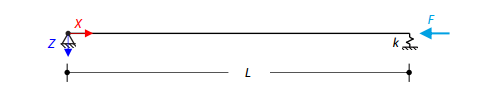
Une poutre en acier chargée axialement avec une section carrée est fixée à une extrémité et supportée par un ressort à l'autre. Two cases with different spring stiffnesses are considered. The verification example solves the calculation of the load factors of the beam in the image using the linear stability analysis.
Une plaque orthotrope carrée en couches est complètement encastrée en son point central et soumise à la pression. Compare the deflections of the plate corners to check the correctness of the transformation.